
Nam June Paik, a seminal pioneer of video art was known for fusing new technologies to create unusual and evocative works that continue to raise questions about the construction of culture. In his early work, the artist began making altered televisions, wherein he manipulated television signals with magnets and used video feedback, synthesizers, and other technology to produce kaleidoscopic shapes and luminous colors.
Paik’s later work included a series of sculptural television constructions–or walls. In 1982, Paik used televisions and video channels to form a configuration of the French flag for the Musée National d’Art Moderne. In 1985-6, he created three works using the American flag: Video Flag X (Detroit Institute of Art), Video Flag Y (Chase Manhattan Bank), and Video Flag Z (Los Angeles County Museum of Art). These works are composed of 84 10” CRT monitors in a 7 x 12 grid within a plexiglass frame.
The Hirshhorn’s Video Flag, acquired in 1996, has significant variations in technology, size, and construction compared with the earlier Video Flags X, Y, and Z, reflecting Paik’s continual integration of newer technologies (see fig. 1). Video Flag incorporated the latest advances in video technology at that time, including LaserDisc players and programmable and custom switchers that merge four video channels into a collage of split-second images and binary numbers.
Fig. 1a, below: Video Flag, 1995, Nam June Paik. Pictured on view at the Hirshhorn Museum and Sculpture Garden in 1996.

Video Flag’s enormous bank of 70 14 in. CRT monitors represents the American flag’s stars and stripes through flashing imagery of technological advances and iconic moments from American politics: news stills, rotating shots of the State of Liberty, scrolling streams of zeros and ones (the binary language of computers), and a morphing sequence portraying U.S. president portraits, from Harry S. Truman to Bill Clinton. The always-present image of the flag serves as a backdrop against which these individual cultural events, personas, and technologies are experienced, recalled, and understood.
As with many time-based media works, quickly changing technologies and equipment obsolescence has necessitated active conservation intervention several times over the course of Video Flag’s life at the Hirshhorn. Shortly after the work’s arrival at the museum, the process of migrating the work from its original LaserDisc players to DVD players began, in collaboration with the Paik Foundation and electronics specialist, Dan Meijer, C.E.T. A popular work in the collection, Video Flag was on frequent view, and other preservation efforts, such as the addition of fans, rewiring, and television assessment and calibration significantly increased the exhibitability of the work in the early 2000s.
In 2015, after over seven years in storage, the examination and conservation of Video Flag became a priority for the conservation department, and a multi-year conservation effort was launched, culminating in the exhibition of Video Flag at the Hirshhorn in the summer of 2019.
As a multi-channel video installation consisting of numerous sculptural and functional components, Video Flag requires robust conservation documentation and treatment. In order to exhibit and preserve complex installations such as this, the elements and behavior that are essential to the work must be accurately examined and contextualized. The task of developing a thorough record of Video Flag’s history and functionality is compounded given the work’s scale, fragility, ever-aging technology, and complexity. This complexity led to the division of conservation goals into three main phases: physical assessment and preparation for display; addressing media technologies and their potential obsolescence and migration; and storage and preparation for loan or travel. Phase 1 included overall in depth examination and documentation of the display technology; identification of condition issues and risk associated with electrical components, fire safety, and ventilation; and preparation for exhibition–monitor repair, calibration, and addressing weak signal flow. This initial phase was completed in June of 2019 and will be discussed here.
Construction and Display Technology
Video Flag’s armature is composed of square welded rods with black painted steel sheets riveted to the exterior, creating a rectangular enclosure with a cavity in the rear that allows access to the backs of the monitors and decks for installation, maintenance, and wiring purposes (fig. 2-3). This entire structure sits on a set of heavy duty casters, allowing the 5000 lb artwork to be adjusted during installation; larger moves require almost total disassembly for safe handling.
Fig. 2, below: Metal armature of Video Flag, during recent treatment.
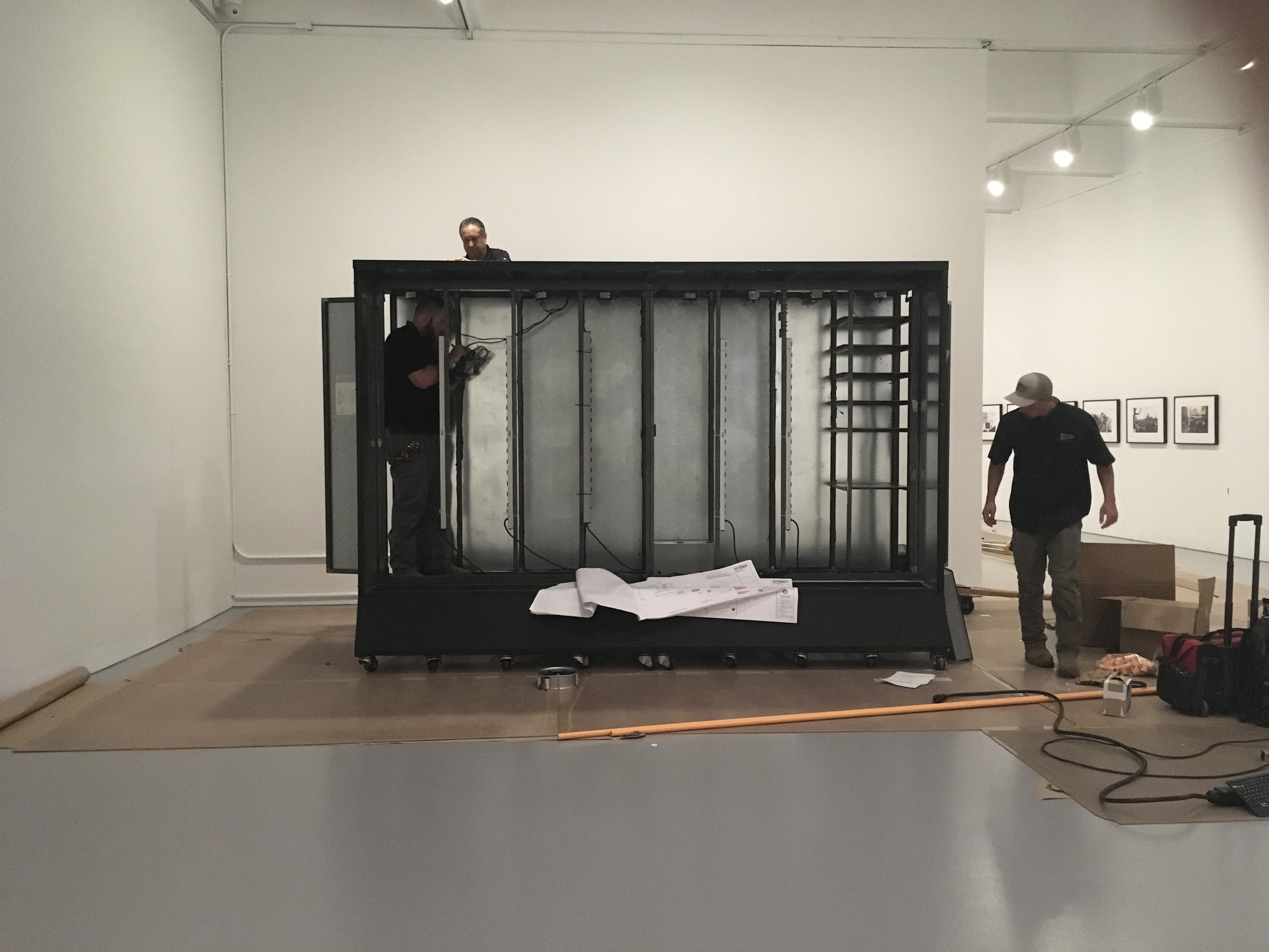
Fig. 3a, below: Interior of the armature. Note the cavity at the back of the work that allows access to cabling and equipment.

Fig. 3b, below: Cabling inside the metal armature.

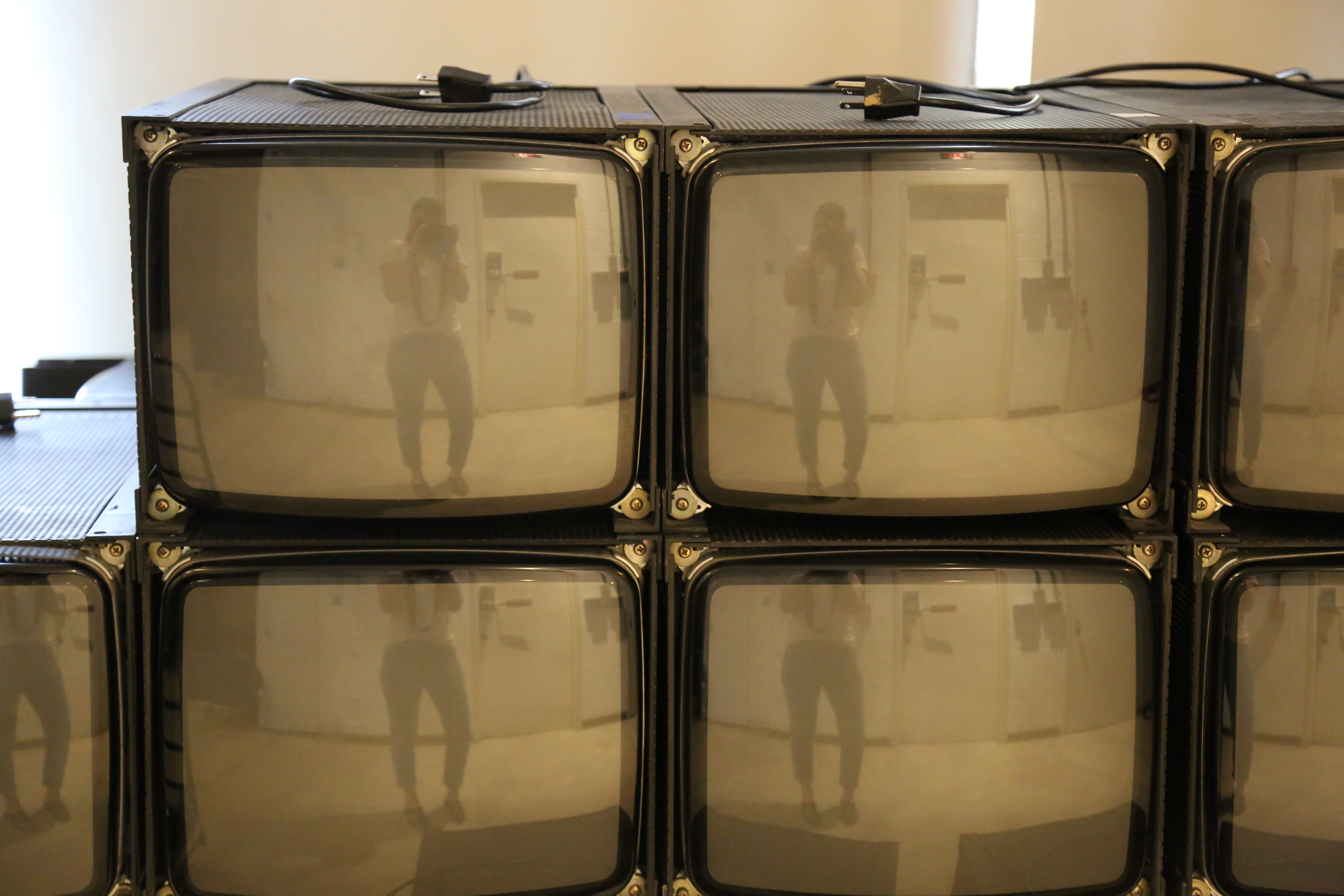
The Samsung 14” cathode-ray tube (CRT) monitors in the artwork were modified by the artist both internally and externally to accommodate custom rectangular metal housings that allow the televisions to be stacked in a 7 x 10 monitor grid (fig. 4). Monitors are inserted into the front of the armature, one on top of the other, and secured with pins. Visually, these stacks of monitors create a “video wall” that functions as a sculptural component, as well as the work’s display technology.
Fig 4, below: CRT monitors in metal housings that allow stacking.
All cabling runs in the rear cavity of the work, accessible by metal doors on the left and right side of the armature. Metal shelves for the playback equipment are welded into the armature on the proper left side of the cavity; while wiring must happen from within the cavity, the equipment controls are accessible from the exterior by the proper left door (fig. 5).
Fig 5, below: Detail of playback equipment housed inside metal armature.

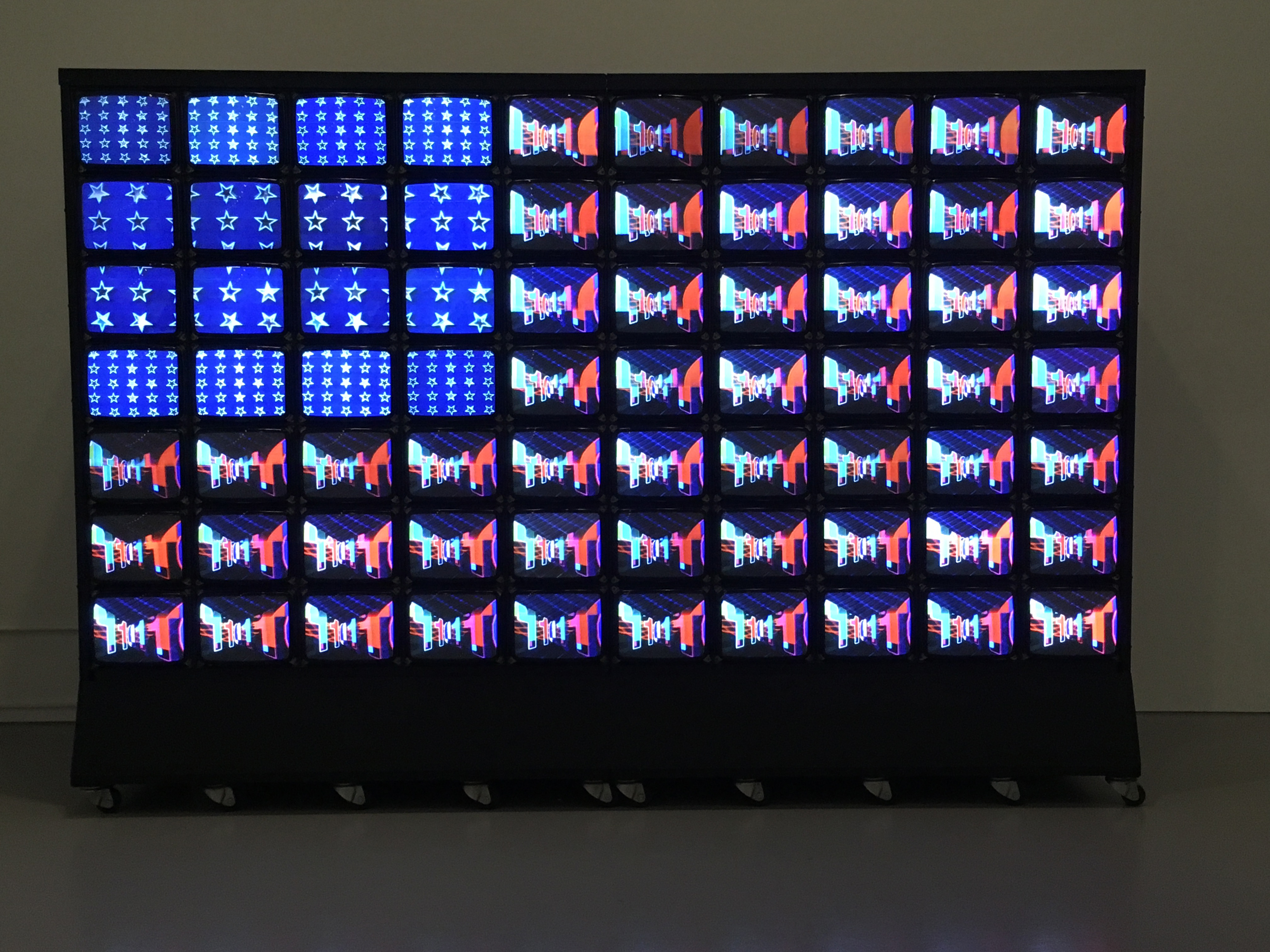
The four video channels comprising the work are currently played from DVD players, with the video signal then running through distinct pathways that give each of these channels their specific flashing behavior and patterned configurations. Mimicking the arrangement of patterns on the US flag, a series of star imagery occupies the 16 monitors in the upper proper right corner. A custom modified commercial multi-screen device allows the imagery from this channel to appear on all 16 monitors or to be distributed across them in various patterns and configurations. The red and white stripes, fed through a switcher, alternate in quick flashes of different lengths with a video of quickly moving zeros and ones (fig. 6).
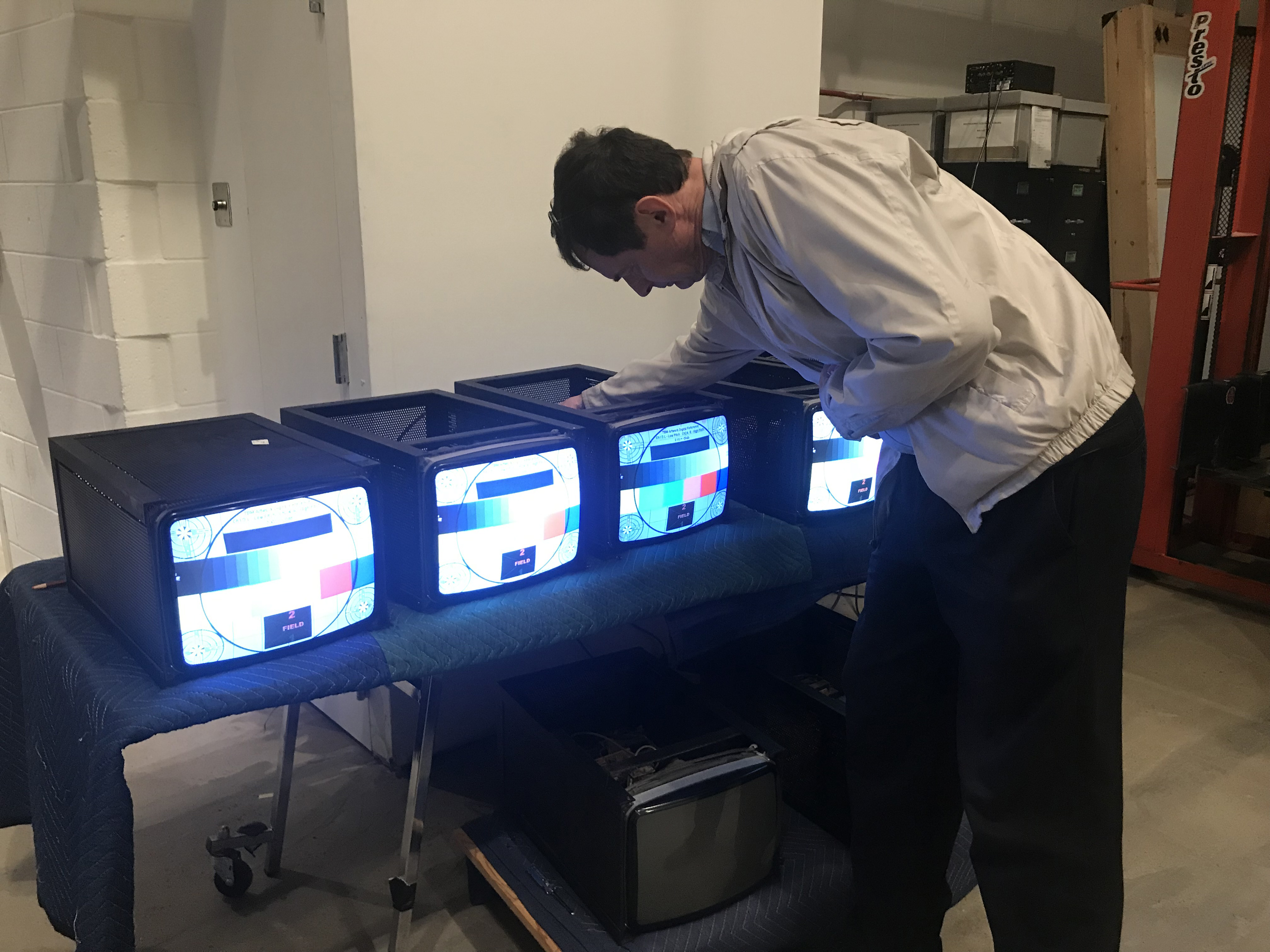
Fig 6a, below: Video Flag, during testing for installation.
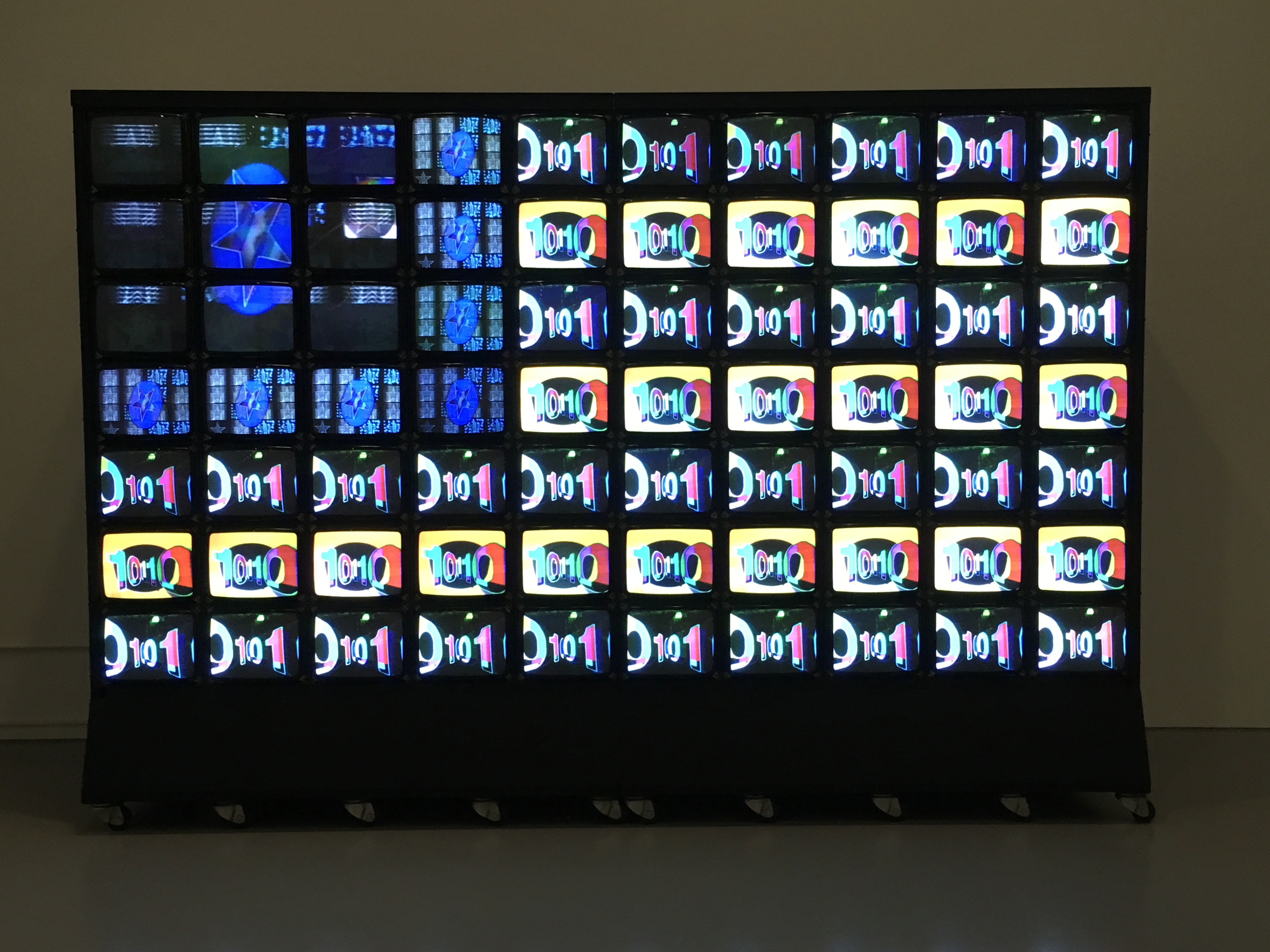
Fig 6b, below: Video Flag, during testing for installation.
Power was originally fed to the entire assembly through the use of 24-outlet powerstrips attached to the inside cavity of the armature; operating the work required access to 60 amps and six outlets, which were triggered manually in previous installations. The power requirements, exhibit functionality needs, safety standards, and artwork monitoring needs prompted an overhaul of the artwork’s electrical system.
Electrical System and Monitoring
During the last exhibition of Video Flag at the Hirshhorn around 2007, the Smithsonian Fire Marshall identified significant risk associated with the closely packed monitors housed in an enclosure, aging equipment, and extensive heat generation, and requested additional precautions be taken the next time the work was on view. Later potential exhibition of the work was stalled by the need to carry out the work required for safe display within the museum.
Identification of Video Flag as a potential fire hazard included two general considerations: the safety of the museum and surrounding artworks, and the safety of Video Flag itself. Museum safety necessitated the use of a fire detection system that would be able to report to museum-wide security networks. The systems needed for protecting Video Flag included an automatic shut off, environmental monitoring, a steady, clean power supply, and increased ventilation to dissipate heat generated by the equipment.
The extent of the work led to a larger project in collaboration with an electrical engineering firm; the Smithsonian Facilities Office of Planning, Design, and Construction; and the Hirshhorn Exhibits and Conservation Departments, drawing on expert consultations with the Paik studio and audio-visual experts and fellow conservators to develop the overall approach and plan. Through this multi-year project, the electrical system of Video Flag was upgraded in preparation for the work’s display in 2019-2020. All electrical work was executed without altering the work in profile or in function, and all supplemental components are removable and replaceable.
Electrical updates included the installation of an electrical panel, single 60 amp receptacle, and a relay within the armature (accessed by small doors on each side of the work). As acquired, the work required plugging in six separate surge protectors, to which all equipment was attached. The newly installed electrical panel instead provides, through one wall receptacle, six separate circuits that feed into the relay. Power strips were replaced with programmable Power Distribution Units (PDUs); these were hard wired into the programmable relay panel, allowing for general timed turn on and turn off. Perhaps most significantly, the electrical panel allowed for the installation of a shunt relay that works with the fire detection system to cut off power to the PDUs–and therefore all equipment–when smoke is detected.
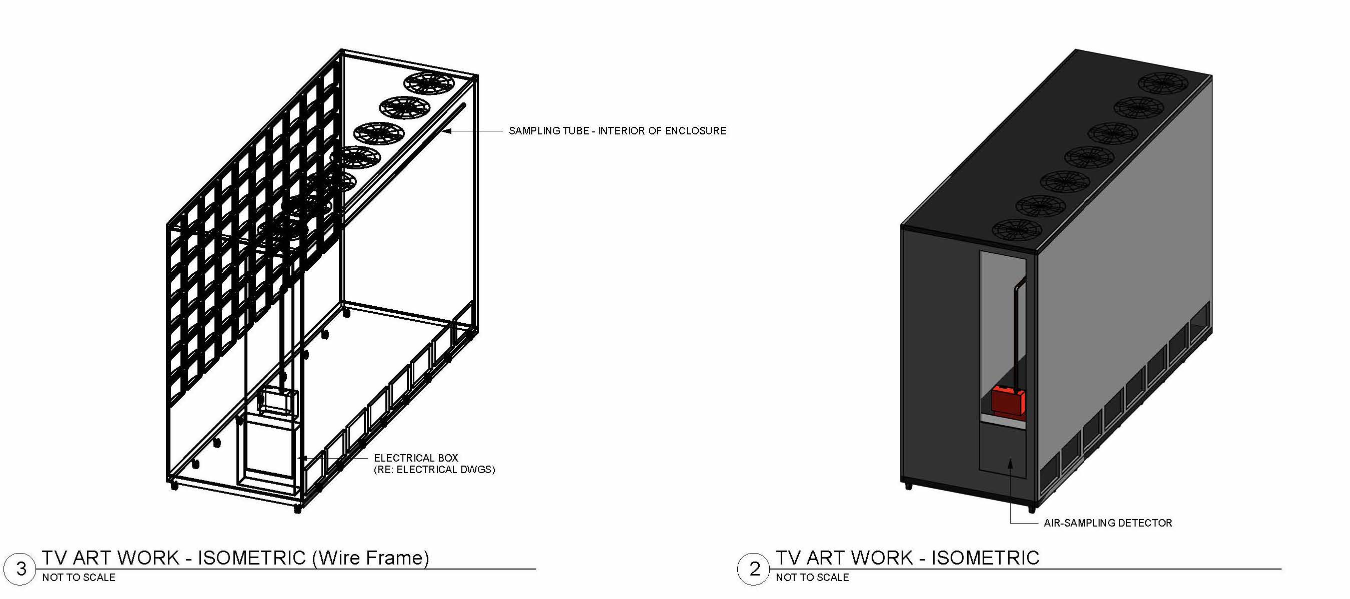
A VESDA VLP detector was inserted in the interior of the cavity of the work’s armature, attached to the lower back wall. This laser-based detection unit, classified as a “Very Early Warning Smoke Detector” detects fire in its earliest stages, with an alarm sensitivity of 0.0015%- 06.25% obscuration/ft. An air sampling pipe was mounted along the inner back wall, just under the fans. Small holes beneath each ventilation fan “sip” the air. When smoke is detected, the VESDA system goes into alarm and trips the power to the PDU circuits (fans, monitors, and playback equipment), leaving power to the VESDA system only. Tripping power in the event of smoke is intended to protect the electrical equipment–including the rare decks and CRT monitors–and to minimize additional fire risks.
All monitors, fans, and decks plug into these PDUs. Each PDU was hard wired to a separate circuit via the relay panel, meaning that each PDU can be powered on separately and each PDU holds the entire load of one circuit, preventing overloading, especially during powering up the monitors. These PDUs can be networked, and each outlet on the PDU strip is individually programmable in powering on/off and recording information. Settings such as turn on and off times can be controlled via a GUI (graphical user interface) over a secure connection, and temperature, humidity, and electricity spikes can all be monitored and tracked remotely. Additionally, certain conditions can be programmed to send email alarms to alert users, vastly increasing our understanding of the functionality of this work over an extended exhibition period and in identifying potential condition issues or points of failure more systematically.
Ventilation
Extended high temperatures are detrimental to the long term operability of CRTs, largely due to the electrolytic (or “wet”) capacitors present inside the monitors. The electrolyte present within these capacitors dries out over time or when exposed to prolonged high temperatures, decreasing capacitance value, and once dry, are rendered inoperable.
The top of the armature enclosure that reaches over the rear cavity has eight voids to allow for the installation of eight fans (see fig. 7). Dan Meijer replaced the original fans with a higher quality model in the early 2000s; this and other alterations done at that time significantly reduced the rate of failing monitors. During examination in 2017, it was determined that additional airflow and cooling would be even more beneficial if it could be achieved in line with the audio and visual requirements of the work, and without alterations to the armature.
Fig. 7, below: Detail of architectural drawing showing placement of fire detection system and electrical panel.
In an effort to extend the life of Video Flag’s monitors, the ventilation system was assessed for its ability to keep the air space around the backs of the CRTs as close to museum room temperature (70-74 °F) as possible. After assessment by an electrical engineer, two main alterations were suggested: a) replacing the fans with a model that moved more air, with variable speed controls to adjust airflow/noise/temperature build up and b) covering open cavities on the bottom of the work to force more air to be pulled from the front of the monitors and up and out the top of the back cavity, providing more efficient cooling. The fans were replaced with a more efficient box fan (51 dbA and 2000 rpm) and additional covering of cavities was assessed after their installation.
Two networked environmental monitors, attached to the PDUs, were placed in different locations within the cavity in order to track temperature changes. At current conditions, the readings consistently register between 72-74 °F, and monitor failure has been tracked at one unit within a 10 month period. Based on this data, and the need for spaces to run cabling inside the work, covering open areas was deemed an unnecessary intervention
Calibration
Concurrent to the electrical and fire safety system installation, thorough assessment of the CRTs was conducted. Though the work is composed of 70 monitors when displayed, an additional 24 back up monitors were part of the original acquisition. All 94 were assessed to determine their basic functionality and the need for either repair or adjustment (fig. 8).
Fig. 8, below: Calibration of monitors. Dan Meijer demonstrates adjustments using controls inside of the monitor housing.
In an effort to learn more about the previous conservation work and to prepare the artwork for display, the conservation team reconnected with Dan Meijer. Together, the monitors were removed row by row from the armature, the tops and backs of the housings were removed, the interiors were cleaned of dust, and they were then calibrated to create the most cohesive image quality possible for the differing conditions of the monitors.
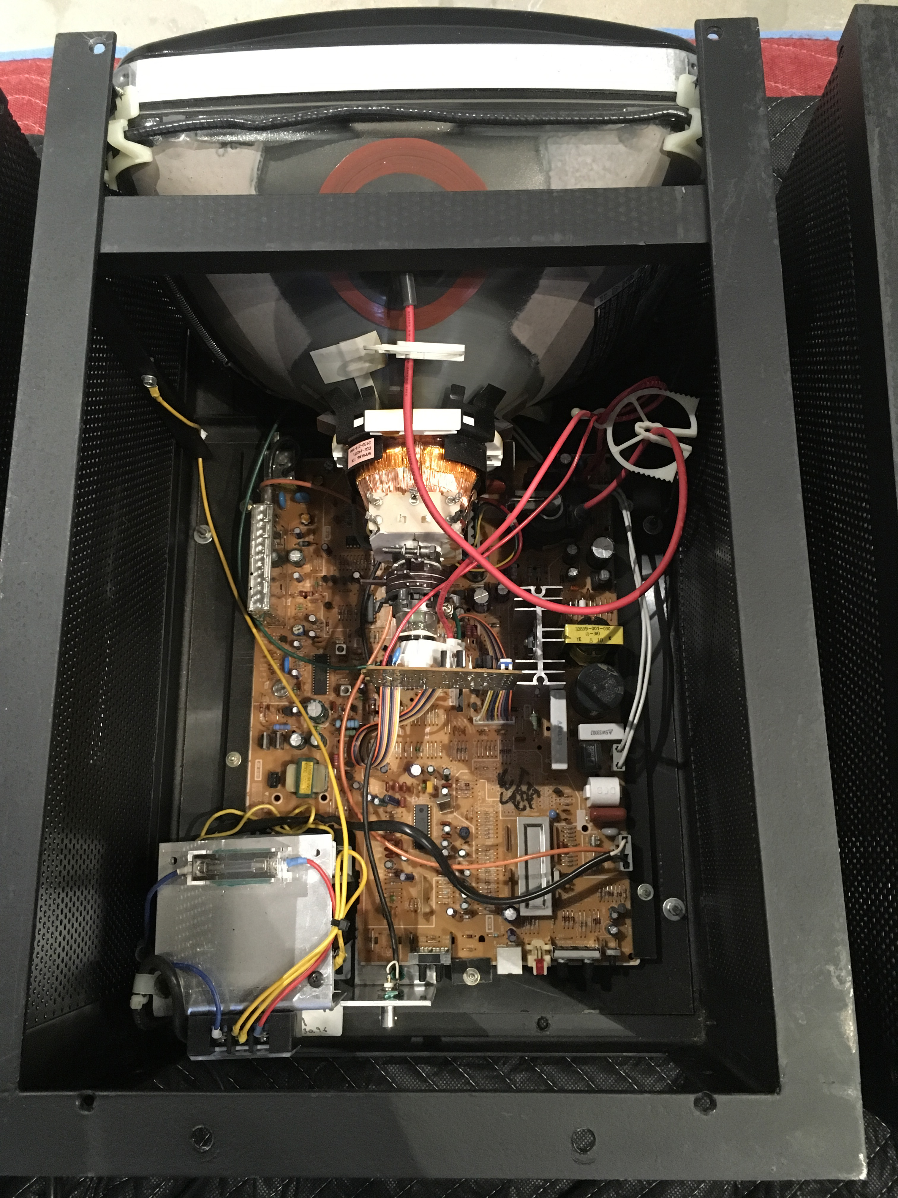
The display of the monitors can be adjusted through either the on-screen menu, or calibrated by accessing the potentiometers on the back of the electron guns of the CRTs. The on-screen menu–only accessible by using a compatible Samsung remote–is in Korean and the IR detector is located on the back of the television, requiring the remote control user to be inside the armature of the work, when the televisions are installed. Through this menu brightness, contrast (picture), sharpness, saturation, and hue can be adjusted. While the brightness, contrast, and saturation settings were helpful in creating a more uniform appearance across all of the monitors and bringing down brightness will extend the lives of the tubes, adjusting the RGB gain and bias levels using the potentiometers has a more significant effect on the color accuracy (fig. 9).
Fig. 9, below: Detail of monitor interior, during treatment.
Many of the monitors have severe calibration limitations due to aging components, limiting the range of luminance and color temperature adjustments. The potentiometers are quite delicate, and a small turn can make a large difference in the picture. Each monitor reacts differently to these changes, compounding the difficulty of making adjustments that read as relatively uniform across the entire bank of monitors.
The 70 monitors residing within the armature when this project began had all been previously used in lengthy exhibitions and can be qualified largely as lightly used to heavily used (5-10%). The 24 extra monitors, however, are composed of heavily used (previously switched out from display), lightly used, and almost unused monitors (striking in their brightness and vividness in comparison to the rest). In order to achieve a more cohesive, blended appearance, monitors were swapped out and moved around. Monitors that were unable to achieve a cohesive appearance due to dim screens or the inability to adequately adjust colors were removed and slated for more extensive examination and repair.
In the past, the work has been installed by simply wheeling the entire armature of stacked CRT televisions into position and connecting to a power supply. During examination, all of the CRTs and playback decks were removed from the armature for assessment both of the equipment and of the structural stability of the enclosure itself. Based on weight calculations (70 monitors at 42 lbs each) and the lack of attachment of the monitors to the structure of the armature, it was quickly determined that safe transport of the artwork necessitated a complete or almost complete deinstallation of CRTs for any significant movements within the building.
The artwork was installed in the exhibition Manifesto, which opened in June 2019, in an outer ring gallery of the Hirshhorn. The armature was installed in the gallery first, and all electrical work was carried out in situ, followed by the reinstallation of all CRTs and all playback equipment (figure 10). The incredible sensitivity of the adjustments on the CRTs necessitated additional minor calibrations once installed.
Having the work on extended view will allow for continued study and planning for future migration of playback equipment that will increase the life of the work.
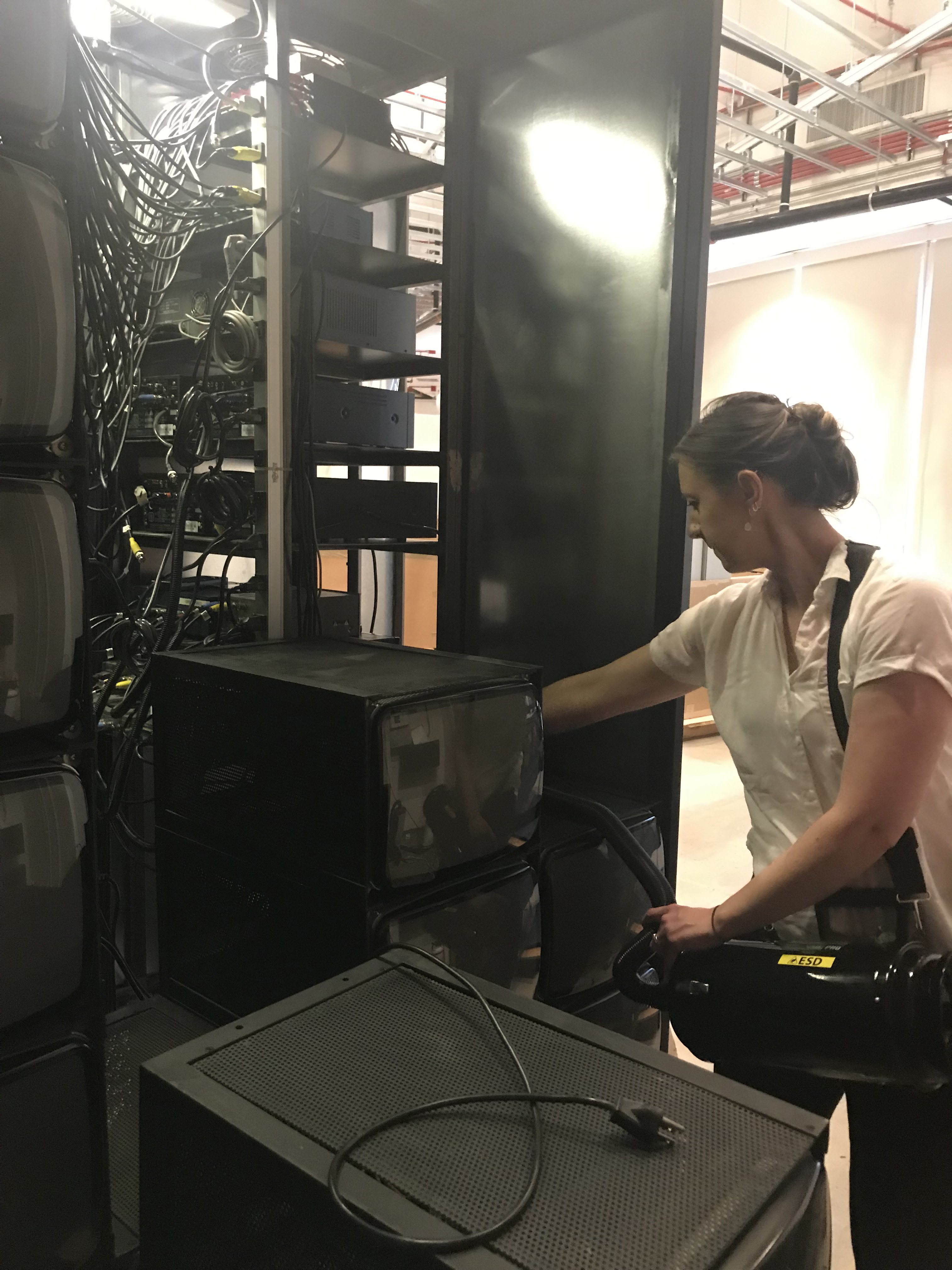
Fig 10, below Installation of Video Flag, during treatment.
"The Hirshhorn Collects: Recent Acquisitions 1992-1996," 4 June-7 September 1997, cat.
"Manifesto: Art x Agency," 15 June 2019-5 January 2020.